
-
Members of the previous forum can retrieve their temporary password here, (login and check your PM).
You are using an out of date browser. It may not display this or other websites correctly.
You should upgrade or use an alternative browser.
You should upgrade or use an alternative browser.
Supercritical CO2 for the Entheogenic Hobbyist
- Thread starter amor_fati
- Start date
Migrated topic.
still working out the last details, for a well-thought out setup.
ordered another swagelok needle valve, and another quick-connect stem. decided to scrap the idea of using a gas cylinder for holding the plant material, in favor of a swagelok whitey 1000cc sample cylinder, like this but without the brackets. It is rated for 1800 psi...not as high as a european scuba tank, but much more convenient/versatile.
my first project will be isolating the flavor oils from roasted pecans.
downwardsfromzero
Boundary condition
benzyme said:my first project will be isolating the flavor oils from roasted pecans.
Yum! Sounds like something that would go nicely in a vaping blend...
or a honey ale 
but with the current setup, infused smoking/vaping blends make great sense too.
but with the current setup, infused smoking/vaping blends make great sense too.
got my 10# CO2 cylinder today (traded for that helium/argon cylinder), still have my empty 20#
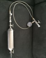
here is my latest transfer assembly setup. plant matter goes into the sample cylinder (going to have a screen inline with one of the valves), I just ordered another SS braided hose and quick-connects, to connect to the sample collection vessel (pictured on previous page). also ordered another needle valve, and a hand-tight valve for the CO2 cylinder, last precautions for venting back-pressure in the transfer line.
here is my latest transfer assembly setup. plant matter goes into the sample cylinder (going to have a screen inline with one of the valves), I just ordered another SS braided hose and quick-connects, to connect to the sample collection vessel (pictured on previous page). also ordered another needle valve, and a hand-tight valve for the CO2 cylinder, last precautions for venting back-pressure in the transfer line.
Attachments
BongWizard
Hyperspace Cowboy
Looking quite professional now benzyme.:thumb_up:
What have you got in mind for the back pressure relief? Personally, I'd go with an adjustable spring loaded relief valve that bypasses the needle valve on top of your sample vessel.
What have you got in mind for the back pressure relief? Personally, I'd go with an adjustable spring loaded relief valve that bypasses the needle valve on top of your sample vessel.
If the manometer is used continually (top needle valve = open) for monitoring what's going on (it's scale support this idea) then there's no need to bypass the needle valve, it's already open. Then on the T-part (where now is a stop in the picture) he can build on a manifold to go on with. If so all components should be max pressure rated.BongWizard said:...What have you got in mind for the back pressure relief? Personally, I'd go with an adjustable spring loaded relief valve that bypasses the needle valve on top of your sample vessel.
I realize vessels should at best be safety-valved without any valve in between, kind of safety-logic.
How will a safety valve look like that operate + 1071 psi?
excellent questions, and the feedback is much appreciated.
in the pic, the tee leading to the vessel has an endcap.. I may replace it with a release valve/burst disc rated for 1800psi, that is the rating for the CO2 cylinder (which also has a burst disc), and the sample cylinder. the line (and all unions, tees, and cross) is rated for 3000psi max., and the valves are rated for 6000psi. max.
....or, I could switch out the tee with a cross, so I can add another needle valve. to that, I could attach the alcohol injection assembly.
Today, I should get a second identical line, a QC stem to the CO2 tank, and QC couplers, to complete the connection from tank to sample cylinder to collection vessel. I will take another pic, it should look interesting.

the original concept was devised by JohnYar Nikoo (JYNdustries LLC), who seems to have removed his videos. He initially used a european scuba tank as his sample cylinder, but it was single ended. The advantage to his approach was the ability to handle greater pressure, but it's still limited to the max. press. rating of the CO2 storage tank.
in my app, I decided to go with a swagelok whitey cylinder. the max press is the same as the storage tank, and it conveniently has two ends, 1/4" FNPT. the modularity is an obvious advantage.
some of you may know, but for those that don't, always use PTFE tape (wound three times around threading) with brass-brass/brass-stainless connections. hand tighten as much as possible, then mark across the coupling and tape with a permanent marker, then tighten 1 1/4 turns (for 1/4" NPT connections).
These rupture disks look neat, cheap, and probably more dependable in their function than a spring loaded relief valve. Drawback: once they're broken they will release the whole content without a stopping. Closing valves manually is the only way to stop the venting, yet coming near a blasting component might be tricky depending on the setup. Yet closing valves to stop venting equals to having no more safety component at all :shock: .
A spring loaded relief valve does better at this: it will will close again by itself after some pressure has been released.
Potential issue: the tuning of the spring pre-load at exactly the value one wants. For this a hand pressure test pump is needed to simulate an over pressure so the spring setting can be adjusted at will. A liquid, like simple water, can be used for this tuning job. Off course when the max setting is already like 1450 psi (100 bar) then it can be set to it's max setting and trust on that without any further bothering. Testing is knowing though.
Another thing worth considering is the amount of trust generated by an opening at those pressures. The structure should not tip over, nor any vulnerable parts (like the body) should be in the potential blast zone.
Normally it should not come to this, but giving it some thought in advance never hurts.
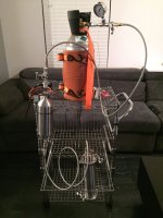
final prototype.
the burst disks won't fit, they're small and not to NPT spec.
I'll start low with the therm controller, like 40-50C, and monitor the temp over 20-30 mins, then adjust as needed.
the tank has its own burst disk, but at those temps, the pressure should be well below max operating pressure (which is well below burst pressure).
btw...extractions will be conducted outside, not in the living room (of course).
Attachments
ok..
I opened the main valve, and the top two needle valves (one after the gauge, and one at top of the sample cylinder), closed them at ~1000psi. no leaks (remember..three rounds of ptfe tape and 1 1/4 turns to swage connections).
gradually opened the needle valve at the bottom of the sample cylinder, and the 140psi relief valve on the collection vessel was activated.
vented everything with the fourth needle valve, located on the tee at the sample cylinder inlet.
around 1400-1500.
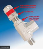
I observed your advice, and purchased a pressure relief valve Pressure Relief Valves - Parr Instrument Company.
A175VB2, set to 1800psi.
I observed your advice, and purchased a pressure relief valve Pressure Relief Valves - Parr Instrument Company.
A175VB2, set to 1800psi.
With CO2 cylinder rating, you mean operating pressure, or max pressure for safety?benzyme said:... I may replace it with a release valve/burst disc rated for 1800psi, that is the rating for the CO2 cylinder (which also has a burst disc), ...
That is within the range of the 1500 - 2250 from the relief valve.
So the RV should be set near it's minimum set-point, it has to open before/near meeting 1800, or the value of the burst disk if it is mentioned.
I suppose minimum value setting of the relief valve is when most of the thread is visible?
It is important to not mistake the min or max setting, at 2250 it will be set too high.
:shrugs:
i guess.
those burst disk valves won't fit, which is why i ordered a PRV from Parr.
i guess.
those burst disk valves won't fit, which is why i ordered a PRV from Parr.
Usually the top cap position (up/down) regulates the spring pre-load.
If it's screwed down --> more spring force, then more process pressure is needed from below to get the spring moving up (= opening of the valve). Meaning a higher set point.
If the cap is screwed upwards (more thread visible), there's less spring pre-load, and at a lower process pressure the valve will open.
If it comes with a drawing this might confirm. Or send them an email to be sure of the min-max setting position.
The top cap has a fine counter nut to unscrew before moving of the top cap is possible.
If it was my setup, I would tune the relief valve setting this way:
- screw counter nut loose from the cap and all the way down to the relief valve body so the cap becomes freely turn-able;
- set the relief valve to max setting 2250 psi by screwing the cap closer toward the counter nut until some end-point resistance shows;
- Open the CO2 delivery tank to bring the system to a certain pressure I wish the relief valve to open on;
- close the delivery tank valve, hopefully the manometer doesn't sink value;
- start to screw the relief valve cap toward a lesser setting until the relief valve starts to leak CO2 out.
- screw counter nut upwards against the cap and tighten, so the setting won't change.
Since the delivery tank valve was closed only a small volume of CO2 would escape.
This way of setting makes sure the relief valve setting is lower than the tank burst disk.
If you want it to set just above 1800, bring system to 1800, lower setting until rv starts to open, turn the cap closer (clockwise) just until the leaking doesn't show up again. Now your just above 1800 set point.
Attachments
BongWizard
Hyperspace Cowboy
Shouldn't the heat source be on the extraction vessel and not the co2 source (given you want the supercritical phase to occur in the extraction vessel)? I only ask because, in my mind (and correct me if I'm wrong), the co2 will lose energy through The Joule-Thompson effect as it passes through the valves, causing it to be sub-critical by the time it enters the extraction vessel.
Similar threads
- Replies
- 4
- Views
- 441
- Replies
- 35
- Views
- 3K
- Replies
- 25
- Views
- 3K
- Replies
- 7
- Views
- 363